1. INTRODUCTION
The Korea Pathfinder Lunar Orbiter (KPLO) mission, initiated in 2016, was launched on August 5, 2022. Its primary objectives include developing technologies for lunar exploration, investigating the lunar environment, and validating new space technologies. Following its separation from the launch vehicle, KPLO embarks on a ballistic lunar transfer (BLT) trajectory towards the Moon (Lee et al. 2020; Song et al. 2023b). Once in lunar orbit, KPLO maintains a polar orbit at an altitude of 100 kilometers above the Moon. Its mission encompasses capturing high-resolution images of the lunar surface, obtaining polarization images, measuring magnetic fields and gamma rays, and imaging permanently shadowed regions. KPLO was designed for a one-year mission in lunar orbit, but after entering lunar orbit, the period was extended by an additional two years, taking into account the spacecraft's condition and remaining fuel.
The KPLO's behavior during the initial and normal operational periods was developed by the System Operations Working Group and validated through system operation tests (Jeon et al. 2018; Jeon 2021). Key considerations in the system operation design included ensuring the orbiter's behavior would be predictable, regardless of its location or time, and enabling it to autonomously respond within the expected parameters in any abnormal situation. Every aspect of the system operation design was tested and verified. This verification encompassed the spacecraft's behavior across all operational phases and the execution of various orbit maneuvering procedures. The confirmed procedures were employed in a series of seven rehearsals. These rehearsals provided launch and early operation phase (LEOP) personnel with opportunities to practice and become proficient in the comprehensive range of initial operational procedures. All early operations procedures from launch to lunar orbit did not deviate significantly from those practiced in the rehearsals (Jeon et al. 2022).
This paper introduces the KPLO system operation design, operation plan, and operation results. Chapter 2 describes the mission operation phases and system operation modes and presents the design results for each phase. Chapter 3 focuses on the early operation plan, operation procedures, and LEOP rehearsals. Chapter 4 presents the results of the early operation, commissioning, and normal operation. Chapter 5 concludes the paper with a summary and future plan.
2. SYSTEM OPERATION DESIGN
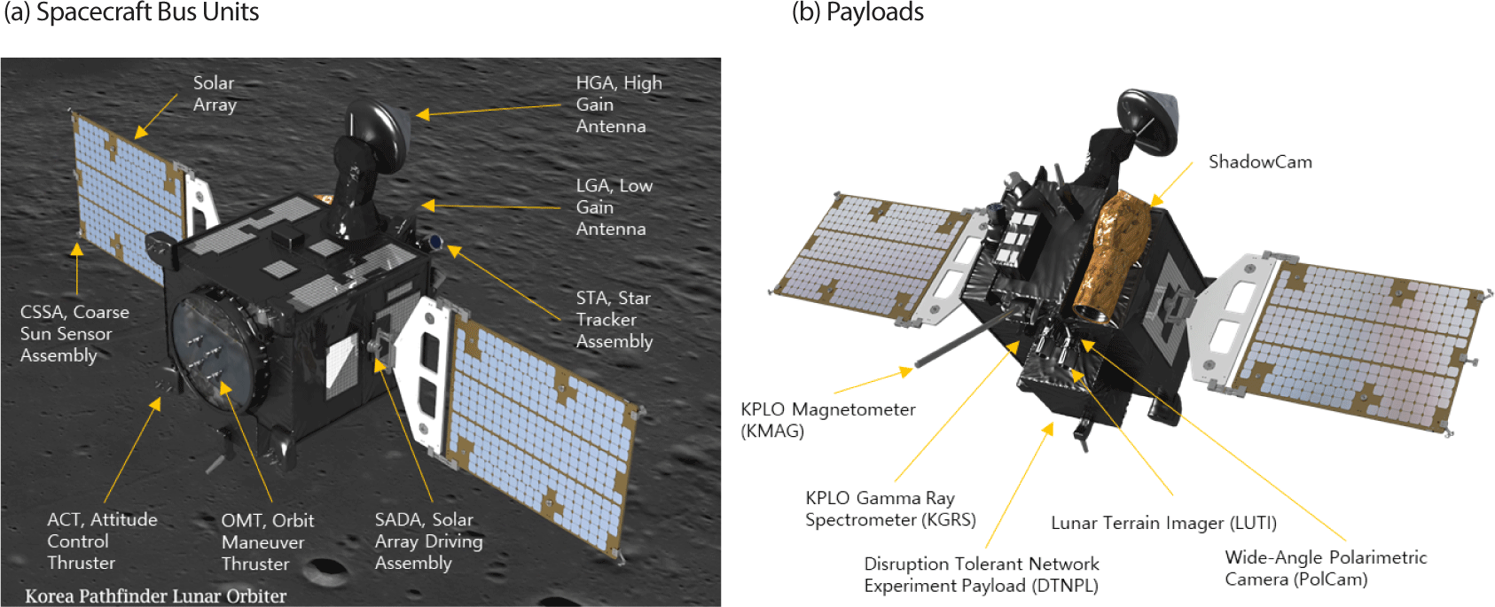
The KPLO system is divided into two main segments: the Space Segment and the Ground Segment. The Space Segment, also referred to as the Spacecraft, comprises the Payload and the Bus. The Bus is made up of several subsystems: structure and mechanisms subsystem (SMS), thermal control subsystem (TCS), attitude and orbit control subsystem (AOCS), electrical power subsystem (EPS), propulsion subsystem (PS), telemetry, command and ranging subsystem (TCRS), flight software (FSW), and payload data transmission system (PDTS). It accommodates six payloads in total. The payloads include lunar terrain imager (LUTI) (Heo et al. 2016), wide-angle polarimetric camera (PolCam) (Jeong et al. 2017), KPLO gamma-ray spectrometer (KGRS) (Kim et al. 2016), KPLO magnetometer (KMAG) (Jin et al. 2017; Jo et al. 2023), disruption tolerant network experiment payload (DTNPL) (Jo et al. 2016; Lee et al. 2022), and ShadowCam (Robinson et al. 2017, 2023; Mahanti et al. 2023). The Ground Segment, or KPLO deep-space ground system consists of Korea deep-space antenna (Park et al. 2023), real-time operation subsystem (Kim et al. 2023), mission planning subsystem (Kim et al. 2017), flight dynamics subsystem (FDS; Song et al. 2021), image calibration & analysis subsystem (Yim et al. 2023), science data management subsystem (Kim 2019). Fig. 1 shows the flight configuration of KPLO. In the flight configuration, deployable devices which are solar panels, high gain antenna (HGA), KMAG boom are deployed.
The system operation method can be divided into two phases. The first phase is from launch to lunar orbit. During this phase, the spacecraft primarily maintains a Sun-oriented attitude, altering its position only during major events like trajectory correction maneuvers and LOI maneuvers to accomplish its mission objectives (Jeon et al. 2023b). The second phase is the operational phase in the lunar mission orbit, during which the spacecraft spends most of its time in a nadir pointing attitude, changing attitude only for special missions. This chapter describes the system operation design results for each of the major mission phases.
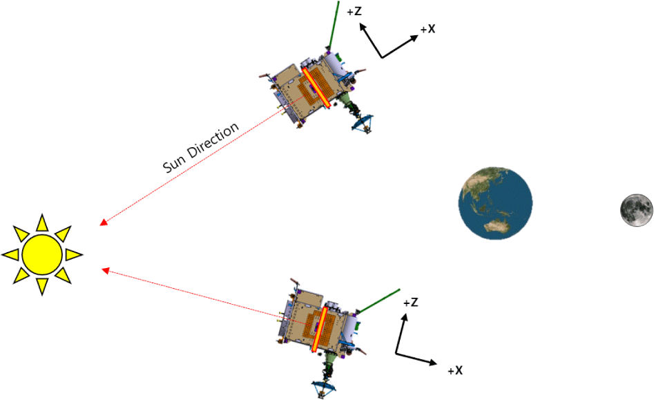
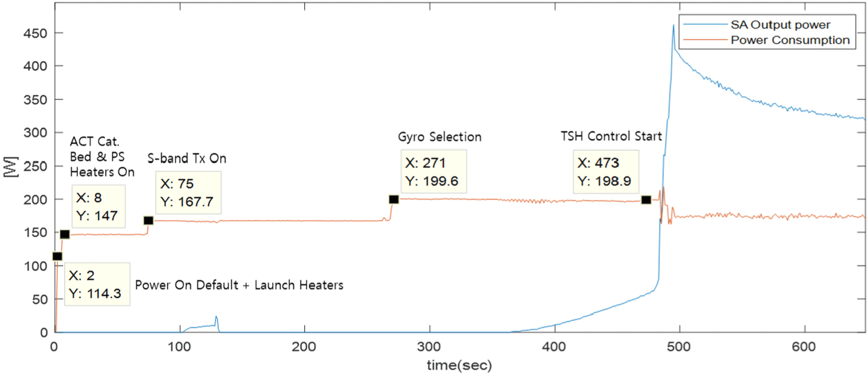
When the KPLO separates from the launch vehicle, the break-wire connected to the launch vehicle is opened, and this signal is recognized to trigger a master reset release event on the onboard computer, which wakes up the FSW. The FSW automatically executes pre-planned initial actions to initiate the first operations of the spacecraft. It starts by turning on the heater to change the temperature of each part of the spacecraft to a range that allows safe mode operation and turns on the S-band transmitter to prepare for ground station contact. The two solar panels are deployed one by one to start generating solar power, and the gyro is activated to prepare for attitude control. The thrusters are then activated and attitude control for sun pointing (SP) is initiated. Fig. 2 shows the attitude of the spacecraft (S/C) during the early cruise phase. In this phase, solar panels are fixed in a home position and points the Sun by controlling spacecraft attitude. The HGA is fixed in the reference position and the low gain antenna (LGA) is used for communication with the ground station.
Upon completing attitude stabilization in the sun-oriented safe mode, the KPLO awaits contact with the ground station. After establishing contact, the operation team checks the deployment of the solar panels and the spacecraft's status, then proceeds with the bus initial activation and checkout (IAC) to transition to normal operation mode (NOM). The first step involves switching both the uplink and downlink from low-speed to high-speed communication modes, and updating the onboard time to the current coordinated universal time (UTC). Subsequently, the heater configuration and operation mode are adjusted to facilitate normal operations, enabling activation of each device. The transponder's ranging function is then enabled, and ranging with the ground antenna commences to determine the spacecraft's orbit. The high-gain antenna, initially secured by Frangi-bolts at launch, is deployed, followed by the activation of its driving electronics. The KMAG boom is deployed using a similar procedure. Once the SP attitude is stabilized, the thrusters are deactivated after checking the overall health of the spacecraft, and the trans-lunar cruise phase begins.
The trans-lunar cruise phase begins once the bus IAC is complete, and the spacecraft operational mode is changed to normal operation mode. This operational phase involves approaching the Moon on a BLT trajectory for approximately 4.5 months, with most of the time spent in a sun-pointing attitude. Fig. 3 shows the spacecraft geometry in the sun-pointing attitude, which is the default attitude for the trans-lunar cruise phase.
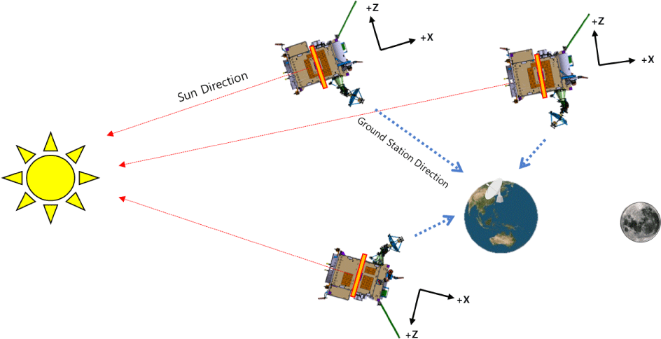
The solar panels are fixed in their home position and oriented to the Sun through the spacecraft attitude control. The difference from the thruster-based safe hold (TSH) Submode attitude in the early cruise phase is that the attitude control is also done in the roll axis. The body -X axis is facing the Sun and the body -Z axis is facing a straight line connecting the Earth and the Sun. This attitude ensures that the Earth is always within the drive range of HGA, allowing for ground station pointing of the HGA. Once the sun-oriented attitude is secured, the HGA ground station pointing logic is activated. Communication with the ground station is then conducted using the HGA. During S-band downlink, the S-band transmitter sends the radio frequency (RF) signal to the selected antenna through the radio frequency distribution unit (RFDU). This means that to communicate with the HGA, the downlink path must be switched from the LGA to the HGA. This RFDU switching procedure is a cold switch operation and must be performed with the S-band transmitter's output turned off. The RFDU reroute procedure is only performed by relative timed command sequence (RTCS).
Routine operations that are performed periodically during the trans-lunar cruise include communication scheduling, state of health (SOH) monitoring, ranging, orbit determination, orbit upload, and wheel off-loading (WOL), and special operations that are performed nonperiodically include trajectory correction maneuver (TCM), HGA calibration, decontamination heater operation for ShadowCam outgassing, attitude control sensor calibration, and Moon or Earth imaging.
The Lunar Orbit Acquisition Phase is the operational phase for entering lunar orbit, which includes preparing for lunar orbit insertion (LOI), LOI maneuvers, and post-insertion actions. In the orbit maneuvering preparation stage, orbit determination and prediction are carried out, and the latest orbit information is uploaded to the spacecraft. Based on this updated orbit data, burn commands are planned. After finalizing the orbit determination, actions that could affect the orbit, such as Momentum unloading, are not performed. Subsequently, both the attitude control thrusters (ACTs) and orbit maneuver thrusters (OMTs) are activated. The thrusters are warmed up using the catalyst bed heater for one hour before use. The battery is maintained in a fully charged status, and the spacecraft maintains a SP attitude. The downlink communication link switches to low-speed communication, and the communication antenna is transitioned from a high-gain antenna to a low-gain antenna. The high-gain antenna is fixed in a predefined position.
The orbit maneuver execution phase performs the orbit maneuver by automated procedures. The operation mode switches from the SP submode to the large angle maneuver submode (LAM) to change the spacecraft attitude to the attitude for orbital maneuvering. Then, in ACT-based delta-V (ADV) Submode, a 100-second liquid settling burn (LSB) is performed using ACTs to stabilize the propellant behavior. This is followed by a main burn in OMT-based delta-V (ODV) submode with OMTs. Depending on required delta-V, the main burn will last for tens of minutes. During the LOI maneuver, the spacecraft enters the orbit at an Earth beta angle of between 70 and 90 degrees to allow communication with the ground station. The operations team at the ground station monitor the execution of the automated procedures and respond to any emergencies by sending ground commands specific to each situation.
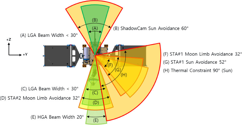
At the end of the orbital maneuver, the spacecraft will automatically switch to SP mode to enable solar power generation. The high-gain antenna begins to point back to the Earth ground station, and the communication antenna switches to a high-gain antenna and the downlink to a high-rate communication link. Both ACTs and OMTs are deactivated, and the orbit is determined using ranging and doppler measurements. Once the orbit determination is complete, we can verify that the orbital maneuvers were completed as planned, and plan the next LOI burn based on these results. For LOI maneuvers, a burn attitude must be derived that satisfies various constraints as shown in Fig. 4. The attitude derivation process is as follows
-
1) Derive the burn start time, burn duration, S/C position, and thrust direction vectors.
-
2) Fix the S/C +X to the thrust direction, and set the -Z to the Earth direction.
, whereas is the thruster direction vector
, whereas is the S/C position in Earth-centered inertial (ECI) frame
-
3) Constraints check (Sun avoidance & thermal constraint)
-
4) If the constraints are not satisfied, rotate attitude in roll axis to find a satisfactory roll angle
Once KPLO enters the lunar mission orbit, it will perform in-orbit tests (IOT) during the approximately one-month commissioning phase to prepare for normal mission operations. The payload line of sight (LOS), i.e., the +Z axis of the spacecraft is oriented to the center of the Moon, and the spacecraft is in an attitude rotated +45 degrees about the yaw axis (+Z) relative to the local vertical local horizontal (LVLH) coordinate system. The reason for the 45-degree rotation is to ensure a certain level of power generation from the solar panels at all Sun beta angles, which is the angle between the orbital plane and the Sun. The solar panels are rotated at an angle that allows for the smallest Sun incidence angle, and the HGA points toward the ground station on the Earth. During this phase, various operations are performed for IOT. KPLO verifies attitude maneuver performance in the LVLH frame and performs initial checkout of each payload. Each payload is commissioned on mission orbit to verify payload characteristics and perform calibration. If special attitude maneuvers are required for calibration, such as star imaging for LUTI or background observation for KGRS, the spacecraft supports the payload mission by operating the spacecraft bus. The mission data of the payload is stored in the payload data handling unit (PDHU) and transmitted to the ground station via X-band transmitter and HGA. WOL from the mission orbit is performed once a day.
In lunar orbit, the Sun beta angle changes constantly on a six-month cycle. When the Sun beta angle passes 0 degrees, a yaw flip maneuver is performed so that sunlight is mostly illuminating the spacecraft’s -Y, -X, and -Z panels.
Upon completion of the IOT and calibration in lunar orbit, the 11-month nominal mission phase begins. This phase involves conducting the standard missions of each payload. All payloads, except for the DTNPL which operates only during special testing periods, will perform regular mission operations. The main operations during the nominal mission phase are categorized according to the execution cycle as shown in Table 1.
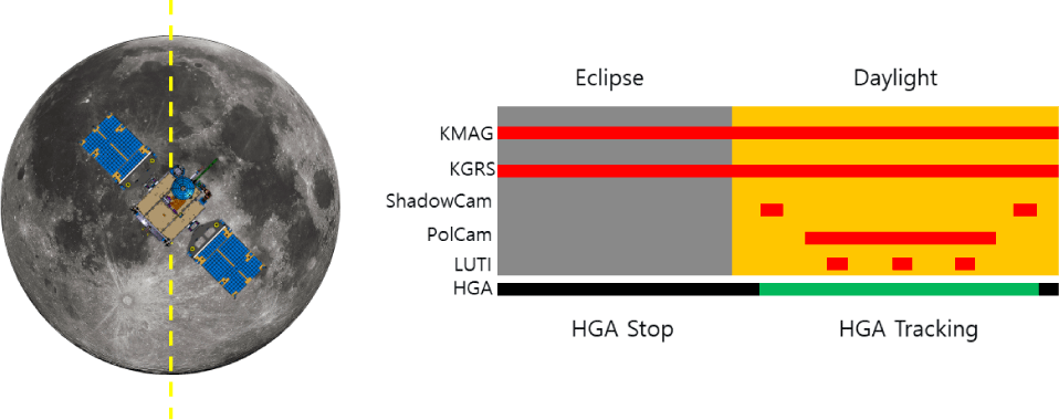
In each orbit, the spacecraft performs operations for payload missions. During the daylight of each orbit, LUTI and PolCam missions are executed, while ShadowCam mission is conducted over the lunar poles. KMAG and KGRS are operational continuously, and DTNPL is activated during specific periods. Ranging is performed at every contact time to determine the orbit. The duration of the ranging can vary depending on the required orbit determination accuracy. Communication with the ground station uses HGA and selects the ground station among deep space networks (DSNs) and Korea deep space antenna (KDSA) that needs to be oriented in each orbit and points to it. Communication with the ground station is performed using S-band communication (tele-command/telemetry) on all passes, with a parallel X-band downlink on certain pre-selected passes. Fig. 5 shows KPLO operation concept in an orbit including instrument operation and HGA operation.
KPLO operates in the defined system mode during LEOP and mission operation phase. If launch, solar array deployment, Sun pointing, and bus IAC are successfully performed, the system mode will be switched from launch mode to sun-safe mode (SS) to NOM which is AOCS SP submode during LEOP as shown in Fig. 6. For orbit maintenance, the system mode will switch from NOM to orbit maintenance mode (OM) to NOM. During KPLO mission operation, the system mode remains in NOM which is AOCS target pointing submode (TP). In case of fail-over due to fault occurrence, it is switched to sun-safe mode. S/C bus mode is a combination of AOCS submode, TCS submode, TCRS downlink mode, etc. and can be considered the same as AOCS submode because in most normal operations, the submode of other subsystems is determined according to the AOCS submode. Mode Transition is required for various operation purposes of the orbiter as described in Table 2.
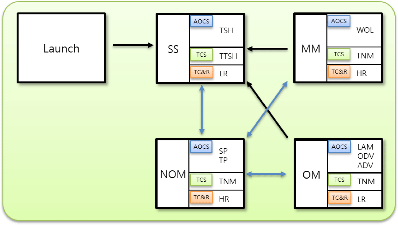
Fig. 6 shows the KPLO mode transition diagram. The system mode consists of SS, NOM, momentum management (MM), orbit maneuver (OM). The AOCS submode consists of thruster-based safe-hold (TSH), WOL, SP, target pointing (TP), large angle maneuver (LAM), OMT based delta-V (ODV), ADV. TCS Submode includes TCS TSH (TTSH), TCS normal (TNM). TC&R has two downlink mode which are low rate (LR) and high rate (HR).
3. LAUNCH AND EARLY OPERATION PHASE (LEOP) PREPARATION AND REHEARSAL
After the system operation design and implementation were completed, an early operation plan was established and operation procedures were developed. KPLO has 265 procedures categorized into early operation procedures, mode transition procedures, unit activation and checkout procedures, spacecraft bus operation procedures, payload operation procedures, and emergency operation procedures. The first one is the early operation procedures which cover key events from launch vehicle separation through commissioning and include ready procedures for various scenarios. The second one is the mode transition procedures which consist of procedures for switching between spacecraft bus operation modes, such as entering NOM, trajectory correction maneuvers, LOI maneuvers, and so on. The third one is the unit activation and checkout procedures which consist of activation procedures for each unit, which are utilized as part of the early operation procedures. The fourth one is the bus operation procedures which utilize the various functions of each subsystem. The fifth one is the payload operation procedures which consist of activation and operation procedures for each payload. The last one is the emergency operation procedures which are performed when urgent action is required in response to a malfunction of the spacecraft. After designing these procedures, system operation tests were conducted to verify the designed procedures. This chapter presents the results of the early operational procedure design and introduces LEOP rehearsals.
The spacecraft bus IAC begins with the first ground station contact after the KPLO is separated from the launch vehicle. The overall health of the spacecraft is checked, followed by unit activation and checks for normal operation. Fig. 7 shows the spacecraft bus IAC flowchart. The procedure is organized in such a way that the status of the spacecraft is checked before any major configuration changes, and if there are no anomaly, the next step is performed. Most of the spacecraft bus initial checkout procedures, including the transition to normal operating mode, are completed by the 8-hour after launch. The spacecraft is then placed in a sun-pointing attitude and the communications antenna is switched from a low-gain antenna to a high-gain antenna at 24 hours after launch.

The bus operation procedure for trajectory correction maneuvers can be conducted in four different ways, depending on the thrusters used and the antennas for communications.
-
1) TCM by ACT burn with LGA downlink
-
2) TCM by ACT burn with HGA downlink
-
3) TCM by OMT burn with LGA downlink
-
4) TCM by OMT burn with HGA downlink
If the delta-V required for a TCM is less than 10 m/s, an ACT burn is implemented; for delta-V greater than 10 m/s, an OMT burn is applied. During TCM, the LGA downlink is used if communication is feasible with the LGA. If not, the HGA downlink is utilized. TCMs are conducted during the trans-lunar cruise phase, wherein the KPLO shifts from a sun-pointing attitude to a burn attitude. The high-gain antenna is fixed at the reference position. For the OMT burn, a LSB with ACT burn is performed for 100 seconds to stabilize the fuel in the fuel tank to the bottom of the tank, followed by the OMT burn. For ACT burn, KPLO performs an ACT burn for the required time without a LSB. At the end of the burn, KPLO changes the attitude back to a SP attitude and resume pointing the high-gain antenna at the ground station.
During LOI, the choice between using a LGA or a high-gain antenna (HGA) for communications depends on the Earth beta angle and the direction of thrust. The trajectory of KPLO is designed such that the Earth beta angle at the time of LOI is approximately 90 degrees. Since the Earth is not in the coverage of the low-gain antenna in the LOI attitude, and communication is possible when the high-gain antenna is in the reference position, a LOI procedure using a high-gain antenna was prepared as shown in Fig. 8.

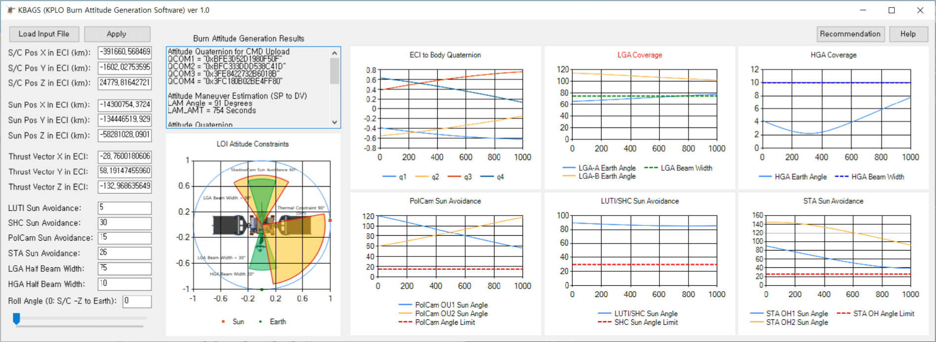
The first step in the LOI procedure is to warm up by turning on the catalyst bed heater, which is usually kept off. Next, the propulsion system components are activated for thruster operation, and settings such as the thruster configuration for the burn, ACT parameters for attitude control, and burn time are established. Burn attitude commands are uploaded in quaternion format, and the burn procedure is uploaded as absolute-timed commands. These uploaded commands are executed automatically at the planned time, with ground control monitoring the execution process. The automatic procedure involves fixing the high-gain antenna to its reference position, changing the spacecraft’s attitude to the burn orientation, performing a 100-second LSB using ACT, and then automatically carrying out the OMT burn for LOI. After the burn, the spacecraft’s attitude is reverted to a sun-pointing orientation, and the final procedures, including thruster deactivation, are conducted via ground command. To generate the burn attitude that satisfies various constraints, we developed and utilized the KPLO burn attitude generation software (KBAGS), as shown in Fig. 9 (Jeon et al. 2023a). KBAGS utilizes the spacecraft’s position, the Sun’s position, and the thruster vector as input parameters. It also checks each angle described in Fig. 4 to verify compliance with constraints while generating the appropriate burn attitude.
After successfully entering lunar orbit through the LOI maneuver, KPLO undergoes an IOT for mission operations before transitioning to a nadir pointing attitude, enabling mission operations. The first step is a check of the current orbit to ensure that the KPLO is in the lunar mission orbit. After entering the lunar orbit, the propulsion system mode is switched to Blowdown mode by closing the Pyro Valve. As no more long-duration OMT burns are required in lunar orbit, and considering the fuel consumption at this point, it is deemed acceptable to switch to Blowdown mode instead of maintaining Pressure Regulation mode. Subsequently, the thermal control system operating mode is changed to TNM mode, altering the control set points of the propellant tank heaters and pressure control assembly (PCA) cavity heaters. Next, the solar array driving assembly (SADA) is switched to Tracking mode to change the attitude of the KPLO to a lunar-centered orientation. Previously, the SADA was fixed at the home position and the solar array driving electronics (SADE) was powered off, but now the onboard logic will automatically control the SADA to minimize the Sun incidence angle onto the solar panels. Once this is done, the spacecraft attitude is changed from the SP attitude to the nadir pointing attitude. KPLO’s nadir pointing attitude is a 45-degree rotated attitude around the +Z axis, relative to the LVLH Frame. After this transition, the spacecraft’s status is checked, and the Sun tracking performance of the solar panels and the ground station pointing performance of the high-gain antenna is verified. The IOT is concluded with attitude maneuver tests using LVLH attitude commands and WOL. Fig. 10 shows the S/C bus IOT Flow in the Commissioning Phase.

During LUTI and ShadowCam missions, attitude maneuvers can be used to point at a target. In this case, the attitude is based on the LVLH coordinate system, allowing for roll axis attitude maneuvers. Fig. 11 shows the spacecraft bus operation for a LUTI/ShadowCam mission.
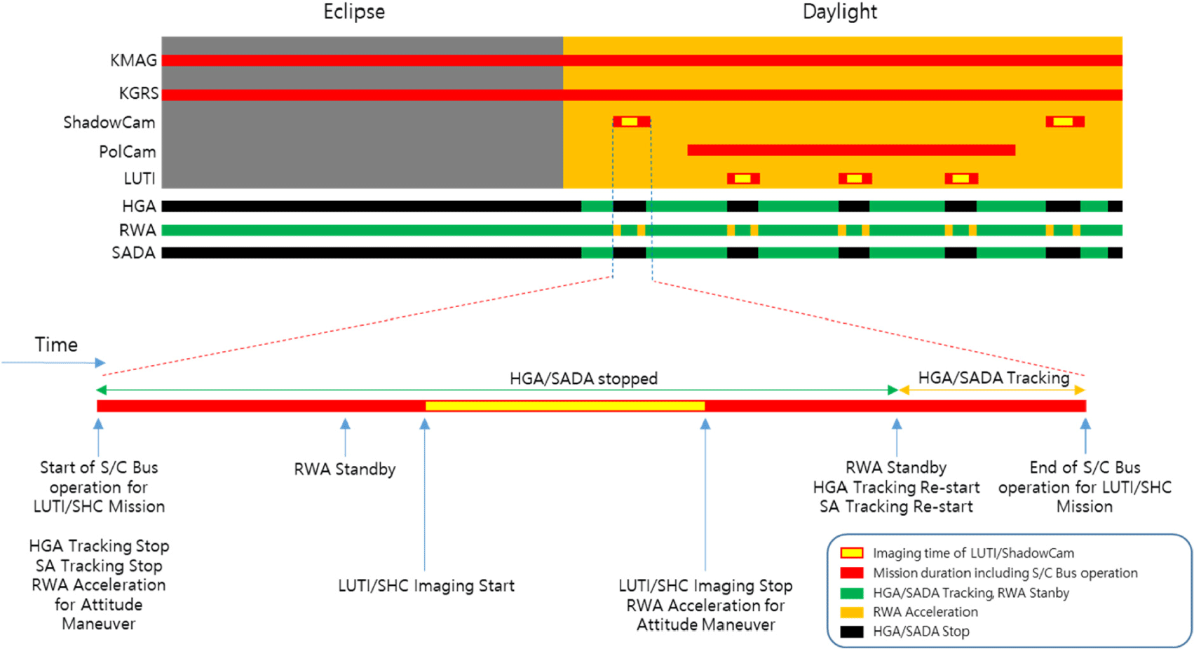
The HGA can point a point in the hemisphere in the direction of the spacecraft’s -Z axis. This allows for 59 minutes of communication, half of one orbit. During LUTI and ShadowCam imaging missions, the HGA must be fixed to prevent jitter. HGA motion is paused before attitude maneuvers and resumed after imaging is complete. During HGA pause, S-band communications will use LGA, and X-band downlink will be discontinued. Taking these considerations into account, the spacecraft bus operation sequence for the LUTI mission is shown in Fig. 12.

KPLO’s orbit is constantly changing in altitude over time under the influence of the Moon’s gravity. To maintain a mission orbit of 100 km ± 20 km, orbit maintenance maneuver (OMM) must be performed every two months. One OMM consists of two ACT burns, as shown in Fig. 13.
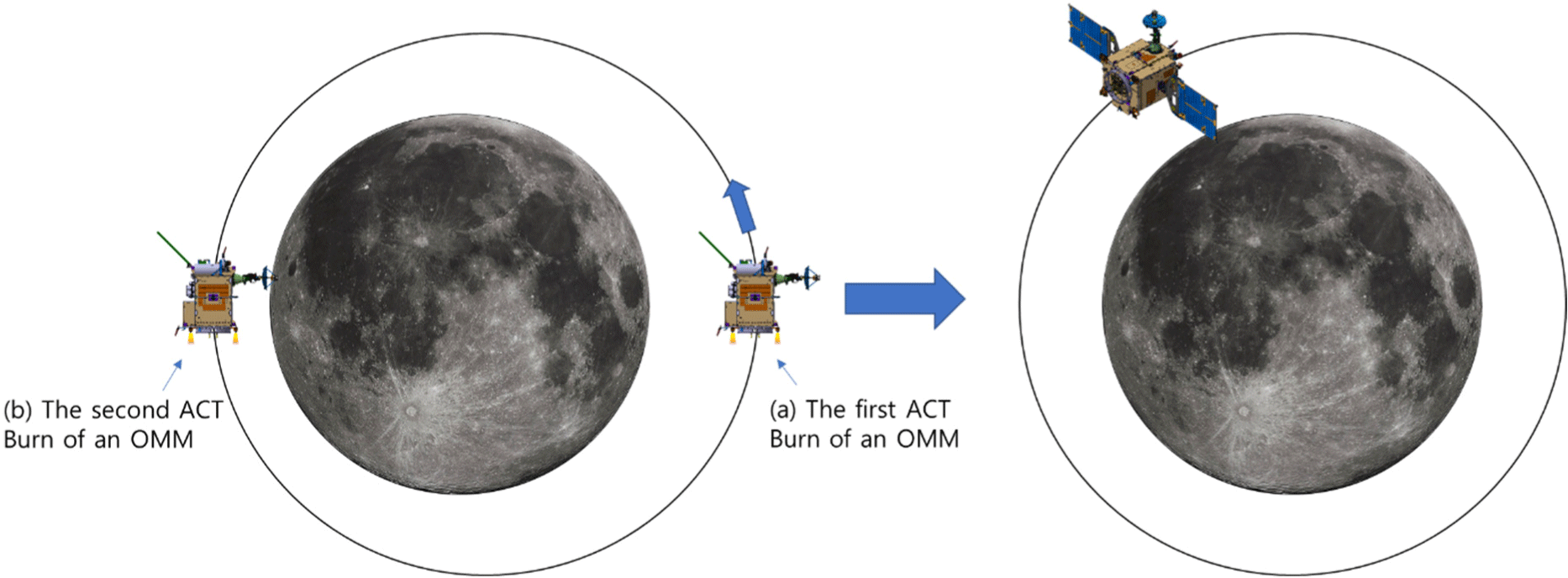
The procedure for the OMM is similar to the trajectory correction maneuver, with the main difference being that the start and end attitudes are nadir pointing attitude. After changing from the nadir pointing attitude to the first burn attitude, the first burn is performed. At the end of the first burn, it switches to the sun-pointing attitude, waits, changes to the second burn attitude, performs the second burn, and switches to the sun-pointing attitude. It then communicates to confirm burn results and spacecraft status before returning to a nadir pointing attitude. The OMM flow is shown in Fig. 14.

The purpose of the LEOP rehearsal is to practice the tasks of the LEOP organization that will be required for early operations and to become proficient in those tasks. The rehearsal is expected to do the following. First, increase the work understanding of each person in the LEOP organization. Second, each team acquires the ability to communicate with each other. Third, improve early operation procedures with real-time-based exercises. Fourth, identify and improve operational aspects of the spacecraft and ground station development deliverables. A total of seven rehearsals were conducted prior to launch, each consisting of a four- or five-day program. The five-day rehearsal program included as much of the LEOP key events as possible. To simulate the actual situation, the control room was connected to the KPLO electrical test bed (ETB) and the early operation scenarios used in the system operation test were applied to simulate the actual situation. Table 3 shows the schedule of the seven rehearsals, and Fig. 15 shows the operational scenarios practiced on each rehearsal day.

4. OPERATION RESULTS
This chapter describes the results of KPLO’s early operations and normal operations. KPLO was launched on August 5, 2022 at 08:08:48 UTC from Cape Canaveral Space Force Station (CCSFS) in Florida, USA, using a Falcon-9. KPLO separated from the launch vehicle approximately 40 minutes after launch and was injected into a BLT trajectory. Shortly after separation from the launch vehicle, the onboard computer woke up and began its initial operations. All initial operations were performed by a pre-loaded command sequence, the Start-up RTCS. The group heaters were changed from the launch configuration to the safe mode configuration, and the S-band transmitter was turned on to wait for the first contact. Both solar panels were sequentially deployed, and SP attitude control using the ACTs was started. By analyzing the stored SOH data, we were able to conclude that the initial operation was successful without any anomalies. Fig. 16 shows the results of power generation and consumption during the initial automated operation. The power profile shows successful attitude control and unit activation.
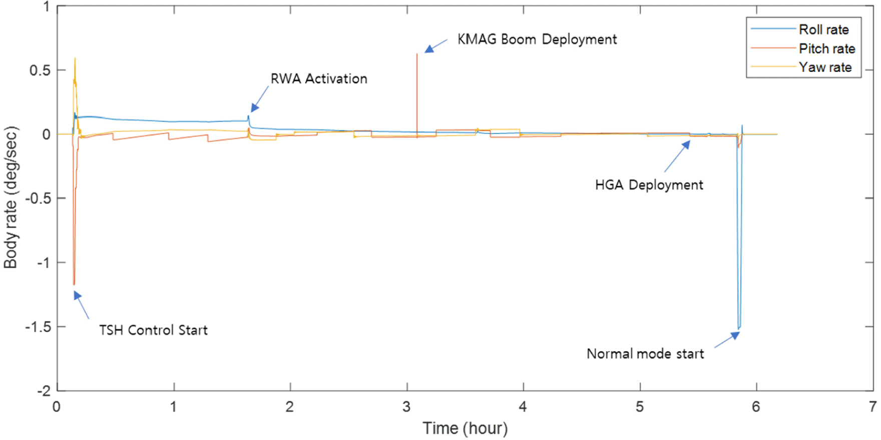
All automated procedures were completed and the first contact was established. The first spacecraft health data received on the ground indicated that all spacecraft health conditions were normal, confirming that the initial automated procedures had been performed correctly. Deployment of the HGA and KMAG then brought the spacecraft into flight configuration. The reaction wheels were then activated after a run-in period of approximately two hours of high-speed rotation, and the star tracker was activated to begin measuring the spacecraft’s three-axis attitude. Using the separation vector information provided by the launch vehicle, an orbit was generated and uploaded, and the spacecraft mode was switched to SP Submode, the normal operating mode. After 24 hours, S-band and X-band communication with HGA’s ground station pointing was initiated, and the stored SOH data was received to check the post-launch status information. Deployment of KMAG boom and HGA was confirmed by the telemetry of each unit and by the change in angular rate of the spacecraft at the time of deployment. Fig. 17 shows the change in angular rate of the spacecraft body during KMAG boom deployment, HGA deployment, and transition to the SP attitude.
The trans-lunar cruise phase started on 6 August 2022 and ended at the end of November 2022. During this phase, the spacecraft mainly remained in normal mode. The solar panel remained fixed in its home position and was directed towards the Sun by attitude control using reaction wheels. The high-gain antenna was precisely pointed at the ground antenna. KPLO travelled along the BLT trajectory throughout this phase. To ensure the intended trajectory was maintained, a total of nine trajectory correction maneuvers (TCMs) were planned, consisting of both deterministic and statistical TCMs. The deterministic TCM was performed successfully, allowing five TCMs to be skipped (Bae et al. 2023). Major events during the trans-lunar cruise phase are illustrated in Fig. 18.
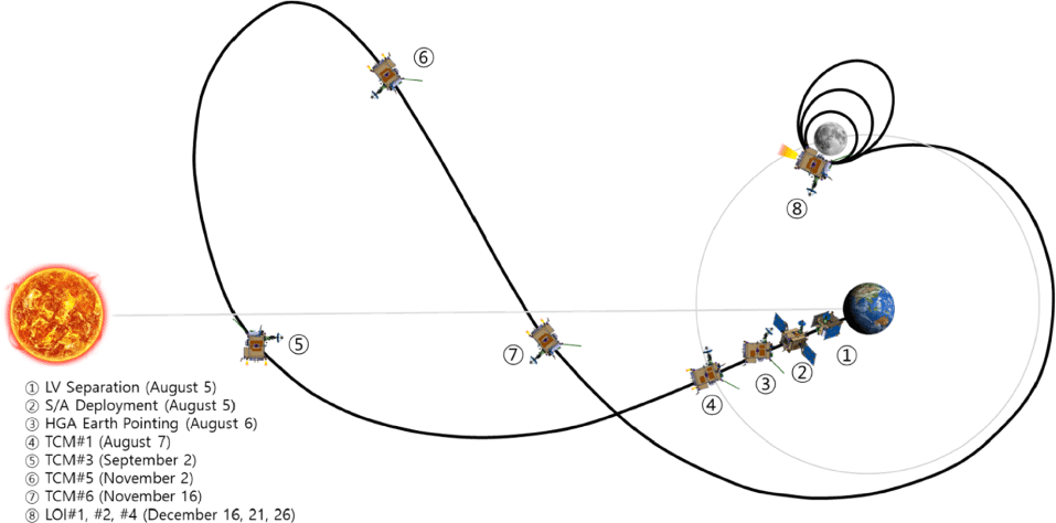
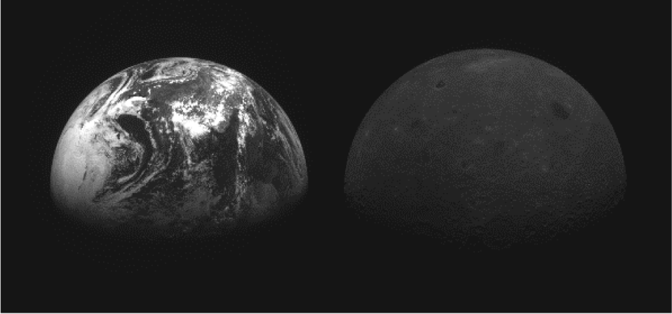
Either OMT or ACT can be used as main thruster for each TCM. TCM#1 and TCM#3 utilized OMT for delta-V burn and ACT for attitude control, while ACT was used for both delta-V burn and attitude control during smaller burns TCM#5 and TCM#6. As anticipated before launch, external disturbances accumulated in the momentum of the reaction wheels. Therefore, weekly WOL was required during the trans-lunar cruise phase. We performed 16 WOLs during this phase. Initially, we performed WOL in a sun-pointing attitude with no attitude maneuvers. Starting with WOL #6, we applied a special attitude to help maintain the designed trajectory. The small delta-V from WOL allowed us to cancel out small statistical TCMs such as TCMs #7–9. During the journey to the Moon, we endeavored to capture unique images of the Earth and the Moon. Fig. 19 shows one of those images taken by LUTI during the trans-lunar cruise phase.
The lunar orbit acquisition phase began with the first LOI maneuver on 16 December 2022 (Song et al. 2023a). The original LOI plan comprised five LOI maneuvers. The first LOI was aimed at capturing KPLO in the Moon’s orbit. The second to the fifth maneuvers, which have almost identical delta-V, were for a reduction in orbit period. Following the success of LOI#1, we combined LOI#3 with LOI#2 and LOI#5 with LOI#4. This alteration afforded additional time for the mission support team (navigation team) and the flight support team (spacecraft specialists) to prepare for the next burn.
At first, the HGA was hold in the reference position and spacecraft attitude was changed to LOI burn attitude. The burn attitude was cautiously selected to satisfy several constraints such as sun avoidance of all optical payloads, thermal constraints, and antenna coverage for communication during burn. After attitude maneuver was completed, a LSB was started and settled down the propellant to the bottom of the propellant tank. Only after LSB, the dynamic model of whole spacecraft including propellant sloshing, solar array flexible mode could be applied to attitude controller for the LOI burn. After the LSB for 100 seconds, the OMT burn was executed for the LOI burn duration. When the burn was finished, spacecraft waited for 2 minutes in the same attitude while controlling the attitude using ACT. This is for reducing disturbance from propellant motion to the reaction wheels after OMT burn. After this waiting time, the spacecraft operation mode was changed back to the SP mode which the reaction wheels are used for attitude control.
Attitude errors during the burns remained below 1.2 degrees, resulting in a precise delta-V in the planned direction. Table 4 shows the burn results for the three lunar orbit maneuvers, and Fig. 20 shows the attitude error for each LOI burn.
| Date | Maneuver | ACT burn time (sec) | OMT burn time (sec) | Delta-V (m/s) |
|---|---|---|---|---|
| 2022-12-16 | LOI#1 | 100 | 672.25 | 143.8 |
| 2022-12-20 | LOI#2 | 100 | 1,125.5 | 260.1 |
| 2022-12-26 | LOI#4 | 100 | 993.5 | 257.2 |

The DSN continued to support the KPLO mission during the lunar orbit acquisition phase from 16 December 2022 to 31 December 2022 (Song et al. 2023c). All three LOI maneuvers were successfully completed, and KPLO entered lunar orbit. Following LOI#2, KPLO acquired an image of the Earth and Moon on 24 December 2022, as shown in Fig. 21, which is known as the “Earth Rise”.

The commissioning phase was started earlier than original plan. After LOI#4, the spacecraft was still in SP mode. The flight support team found there were temperature increase of some units. This was because the spacecraft was affected by direct sunlight and reflected sunlight from the lunar surface. The spacecraft thermal design was optimized to the nadir pointing attitude, so we decided to start commissioning phase as soon as possible. So, a day after LOI#4, the commissioning phase was started. The SADA was turned on and started to track the Sun. The spacecraft attitude was changed from the SP attitude to the nadir pointing attitude. The reference frame for attitude control was changed from inertial frame to LVLH frame. After an attitude maneuver test and a WOL test in LVLH frame, the spacecraft bus IOT in commissioning phase was finished. Then the payload operation in commissioning phase was started. All payloads successfully performed commissioning. Ground system functions for nominal routine operation were stabilized during the commissioning phase. The orbit trim maneuver for precise maintenance of mission orbit was performed on January 16, 2023. A pair of two burn were executed for the orbit trim maneuver (Hong et al. 2023).
The pyro valve was opened on the first day after launch and all orbit maneuvers, including TCM, LOI, and orbit trim maneuvers, were performed in pressure regulation mode. Pressure regulation mode could not be maintained for the entire mission lifetime because the tank was still under pressure from the pressurizer. Considering the remaining fuel and the expected characteristics of future OMMs, we switched to blow down mode by closing the pyro valve on January 26, 2023. On February 3, the Sun beta angle passed 0 degrees, and a yaw flip maneuver was performed. Previously, the yaw axis was rotated by +45 degrees relative to the LVLH frame, i.e., the S/C body +X-Y direction was facing the velocity direction, but from this time, the yaw axis was rotated by +225 degrees relative to the LVLH frame, i.e., the S/C body -X+Y direction was facing the velocity direction. After the yaw flip maneuver, each payload’s mission plan was also updated to reflect the changed attitude. The Sun beta angle passed through 0 degrees once more on August 6, 2023, and the yaw flip maneuver was performed again.
During the one-month commissioning period, a special mission was conducted to capture the phase change of the Earth. Just as we can see the Moon’s phase change from the Earth, the Earth as seen from the Moon also changed its phase over the course of the month, and the results are shown in Fig. 22.

During the nominal mission phase, routine operations were performed most of the time. LUTI captured up to 50 minutes per day of major areas of interest, such as landing sites, while PolCam captured mid-latitude areas within 60 degrees latitude on every orbit. ShadowCam imaged permanently shadowed regions of the Moon’s north and south poles for up to about 40 minutes each day. KMAG and KGRS were always turned on and performed their missions continuously. From February to September 2023, LUTI acquired a total of 4,260 images of the lunar surface, in addition to specially acquired landscapes of major craters such as Tsiolkovsky Crater and Amundsen Crater using attitude maneuvers. Fig. 23 shows a view of Tsiolkovsky Crater taken on March 23, 2023.

Starting with the first OMM on March 9, 2023, a total of five OMMs were performed through October. Each OMM consisted of two burns, each generating delta-V of approximately 7 m/s to maintain the mission orbit within 100 km ± 20 km. During orbit operations, conjunction analysis with other spacecraft in the lunar orbit was utilized to ensure safe operations. In particular, on June 21, 2023, a collision avoidance maneuver (CAM) was performed to reduce the risk of collision with Chandrayaan-2, another orbiter in lunar orbit. Table 5 shows the results of the OMMs and the CAM.
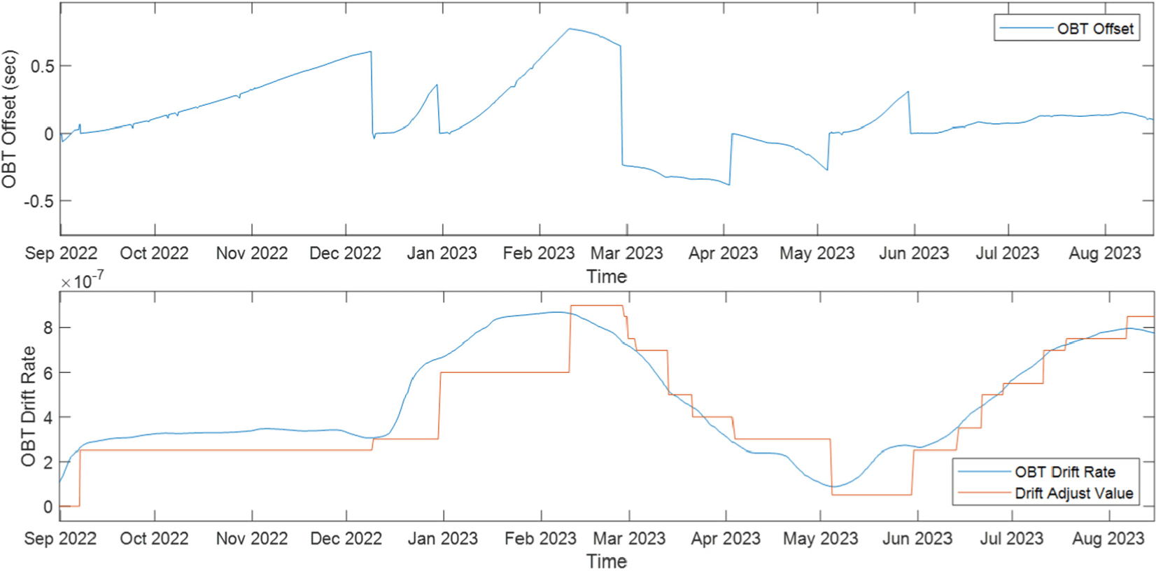
The on-board time (OBT) contained in the telemetry received from the orbiter at the time of the contact deviates from the precise UTC known on the ground due to a number of factors. These include uncertainty in the timing of the on-board computer’s 1 pulse per second (PPS) delivery, the time it takes to generate and deliver the OBT to the S-band transmitter, uncertainty within the S-band transmitter, propagation time from the orbiter to the ground station, and the delay between reception by ground station equipment and recording of the time. By understanding these delays and accounting for them, we calculated the precise OBT value that should be set, and monitored the OBT Offset, the difference from the current OBT, and the Drift, the amount of change in the difference. If the OBT Offset and Drift increased, we either synchronized the time or adjusted the Drift to keep the OBT Offset within 200 ms. Drift was adjusted by changing the number of clocks within 1 PPS generated by the onboard computer. Fig. 24 shows the trends in OBT Offset and Drift Rate from launch through the end of September. Six OBT synchronizations and 20 drift adjustments were performed.
5. CONCLUSIONS
The KPLO operated successfully during all phases from launch to normal operations. All of the IAC performed immediately after launch were carried out as planned, and the trajectory correction maneuvers in the trans-lunar cruise phase were also successfully performed. As the orbital maneuvers were repeated, the characteristics of the thrusters were precisely characterized, and five of the nine trajectory correction maneuvers could be skipped. LOI#1, the first long OMT burn to be performed in lunar orbit, was also successfully performed, and the thruster characteristics were characterized enough to merge the next four LOIs into two. During the LEOP, KPLO attempted a special imaging event that was not planned prior to launch. KPLO was able to capture stunning images of the Moon orbiting the Earth, the Moon appearing the same size next to the Earth, the Earth rise, and the Earth’s phase change. The precision with which the launch vehicle placed KPLO into orbit at launch, and the accuracy with which the trajectory correction maneuver and LOI maneuver were performed, allowed the spacecraft to save fuel that had been allocated for contingency. After entering the lunar orbit, the remaining fuel was analyzed and it was determined that the spacecraft could operate for two more years than the original mission duration. After further analysis of the spacecraft health and power budget, KPLO’s mission was extended by two years. KPLO will continue to carry out scientific missions and will be able to operate safely during the lunar eclipses that occur twice a year. In 2024, the mission will continue on the nominal mission orbit, and the 2025 mission orbit will be determined based on the payload mission and spacecraft operations. The successful operation of Korea's first deep space mission reported in this study will be a very useful experience for the planning and realization of future Korean deep space exploration plans, such as the Mars and the Sun-Earth L4 missions.
