1. INTRODUCTION
Outer space is considered a radiation environment for satellites due to the existence of different rays. The physical and chemical reactions of this environment greatly affect the performance and lifespan of electronic devices and equipment, including memories, transistors, microcontrollers, and microprocessors. Many of these parts and equipment must be strengthened to work in radiation environments. If these devices are not resistant to the radiation environment, they will suffer a lot of damage, which will cause various harmful effects based on the type of radiation, the frequency and the type of radiation interaction. If the amount of these damages is more than the tolerance of the electronic part, that part will fail and in the worst case, all the systems may be disturbed and the project will face a complete failure.
Therefore, it is not possible to guarantee the survival and success of a space system in the environment of space radiation without considering the effects of radiation and reducing them. Since satellites and other space systems are designed to work in the space plasma environment, they are trapped against high-energy particles and are slightly vulnerable. Space radiations caused by solar events or cosmic sources _when they hit and interact with the surface of satellites and spacecraft_ can affect the space system and electrical components in it in several ways (Nwankwo et al. 2020). The three main categories of these effects are total ionizing dose (TID), single event effect (SEE) and damage displacement (DD) (National Academies of Sciences, Engineering, and Medicine 2018; Blachowicz & Ehrmann 2021). Cosmic rays are mainly composed of energetic charged particles. The three natural sources of cosmic rays are: trapped rays, cosmic rays and solar particles. Earth’s magnetic field traps low-energy cosmic rays and solar particles and forms a radiation belt around the earth. Most of the rays trapped in this belt are protons and electrons. High-energy cosmic particles (25 MeV–20 GeV) include all atoms and stars which are created due to the supernova process. Approximately, 88% of cosmic rays are hydrogen, 10% helium and the remaining 2% other heavier atoms. Solar particles consist of two types of radiation, which are: 1) low-energy solar wind particles that are continuously emitted from the sun. 2) Solar particle events (SPE events). These energetic particles have a high flux and can be extremely dangerous for space systems (Tripathi Ram 2011; Rudychev et al. 2023).
It is very important to choose the appropriate radiation reduction method and combine it with the purpose and concept of the mission at the beginning of the design phase. The most known method of environmental reduction is conservation. Obviously, the use of shielding to reduce the environmental effects leads to an increase in the weight and mass of the satellite. Consequently, the design and construction of the shield has always been under the influence of the mass factor and the radiation environment (Daneshvar et al. 2021).
The most common radiation protection for satellites is to add aluminum to reach the desired radiation level. However, in environments such as the geostationary Earth orbit (GEO) orbit where electrons are dominant, thick aluminum walls are not the most efficient radiation shields, because they are able to weaken the secondary X-rays caused by the collision of electrons with matter. As a result, they are not protective. In general, materials with a higher atomic number, such as tantalum, can greatly weaken X-rays, but when used as electron shielding, they create more secondary X-rays and weigh more. They also impose more on the system (Narici et al. 2017; Lei et al. 2023). Today, polyethylene is considered a suitable protection for the space environment due to its high hydrogen surface, low density, ease of use, reasonable price, and since it prevents nuclear fission processes (Xu et al. 2022). There exists another lighter protection shielding called “multi-layer Graded-z” which not only is protective against energetic protons but also works well in electronic environments. The design of these types of shields usually includes three layers. The first layer is a light material to minimize the production of X-rays. This layer, when hitting electrons and due to its low density, weakens the electrons and produces less secondary radiation as well. The second layer is a material with a higher atomic number to maximize the attenuation of the X-rays produced in the first layer. In the third layer, substances with low atomic number are used to weaken the secondary electrons by producing minimum secondary X- rays. In this structure, the material of the middle layer with a high atomic number does not cause the production of secondary X-rays since the electrons in the primary layer are weakened (Arif Sazali et al. 2019; Hussein et al. 2020; Vepsäläinen et al. 2020; Rudychev et al. 2023).
In the design and construction of radiation shields, choosing the appropriate material and thickness of the layers is essential in reducing the dose and optimizing the weight. This requires experimental and computational work. Despite the greater accuracy of the experimental method, using computational and simulation methods can be time-saving and cost-effective since the practical tests demand high expenses, a long time to be implemented and access to space radiation testing laboratories (Rahman et al. 2017; Li et al. 2018; Shoorian et al. 2019).
2. METHODS
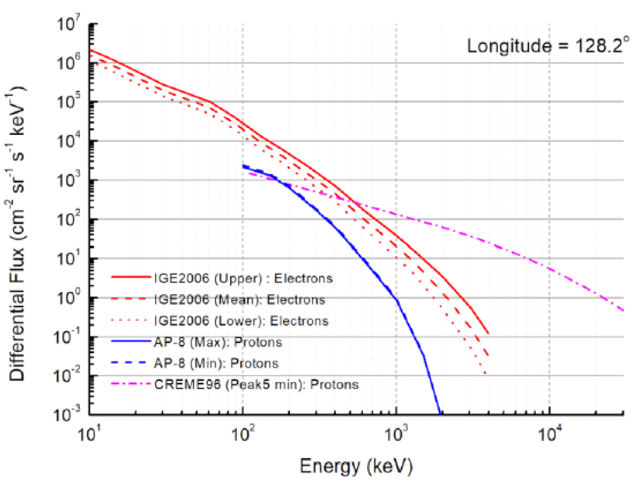
The energy and flux of space rays can be provided by using the space environment information system (SPENVIS). SPENVIS is an online software which models the space environment (including cosmic rays, natural radiation belts, energetic solar particles, plasma gas and micro particles) and its effects. In this work, the radiation environment of GEO orbit as a strategic orbit for telecommunication satellites has been investigated. In the modeling of trapped rays, the AP-8 model for protons (Fig. 1), which is a statistical model and covers the radiation belts completely, has been used (Seon et al. 2020; Liu et al. 2022).
One of the powerful tools in the field of dosimetry calculations of all types of ionizing radiation is the MCNPX code. This code is a Monte Carlo beam transfer software that tracks all particles at almost all energies. In this work, Tally F6 of MCNPX code is used to obtain the energy left by the particles and dose calculations. When using this method, if the transport of secondary particles is not considered and they are not included in the mode card, it is regarded to leave the energy of these particles in the place of interaction (Ferrari et al. 2018).
The other software in this field is MULLASSIS, which uses the Geant4 radiation transfer toolbox to simulate particle transfer in one-dimensional flat or spherical shields. This instrument can be used to determine particle attenuation, ionizing radiation dose and non-ionizing dose, and energy deposition at pulse height as a function of material shielding.
However, for better and more convenient use, MULASSIS is available through the SPENVIS website, so that the user can control the Monte Carlo simulation remotely using a web browser. In the web-based version of the MULASSIS software, the user is presented with a series of web pages that allow him to define geometry and materials used, source particle energy and angular distribution, physical models and particle shear applied, and definition web page analysis requirements. The geometry allows control over the type of geometry (flat or spherical), the number of layers that the shield includes, the thickness of each layer and the composition of the simulated materials.
Therefore, the focus of protection in this work is polyethylene and light elements. In accordance with the points just mentioned and taking the importance of the weight factor in the design of space systems into consideration, this factor has been regarded as one of the criteria for optimizing the thickness of the designed shielding layers in comparison with the aluminum shielding. The conditions of radiation environment for all investigated modes of these shields are considered the same, which include a mission in GEO orbit and is provided by the SPENVIS (Seon et al. 2020). In this work, a multi-layer shield consisting of polyethylene, water and aluminum has been introduced and its performance has been compared with aluminum shield, as the most common radiation shield. Finally, the optimal structure has been selected according to the TID attenuation and shielding mass. The Monte Carlo calculation approach of the MCNPX code and the MULLASSIS code from the Geant4 radiation transfer toolbox have been used to calculate the dose attenuation of various materials in the environment and for a telecommunication satellite with a mission in the GEO space orbit.
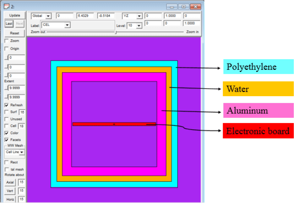
The composition of protective layers, whose design is based on the multi- layer structure, is shown in Fig. 2. The first layer is chosen from the outside of polyethylene to minimize the production of X-ray bremsstrahlung. After that, the layer is made of water, so it weakens the braking X-rays produced in the polyethylene layer. Since electronic devices are usually placed in aluminum boxes, it is placed at the end and the innermost layer of aluminum.
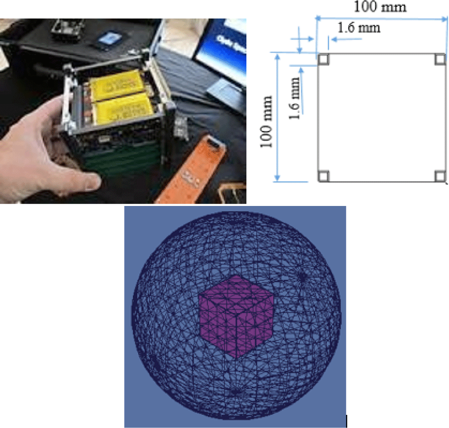
The studied satellite protection structure is a cube-shaped structure made of aluminum alloy 7075 made by CUBESAT Company and has known dimensions according to Fig. 3, which is simulated by MCNP software (ISISPACE 2024).
Most of the standard commercial electronic components usually have problems in the (30–30 kilo rad) dose range (Mahadeo et al. 2018). In this work, dose is obtained by using Tally number (F6) with a suitable number of records which reduces the statistical error below 1%. The source energy distribution and probability have been calculated using the output obtained from SPENVIS for the mission, with the particle flux in each energy being considered as its probability.
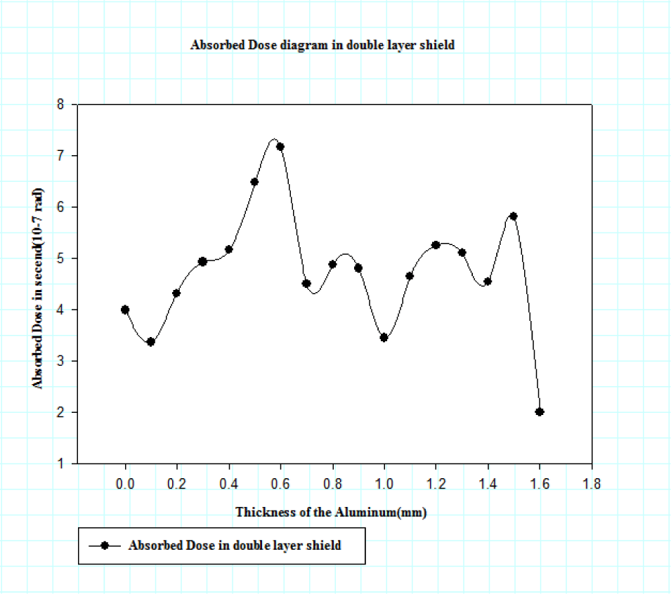
Table 1 contains calculations of the dose caused by trapped particles in the MULLASSIS code based on changes in the thickness of aluminum and polyethylene. It can be seen that by changing the thickness of aluminum (reducing the thickness of aluminum) and adding polyethylene as the second layer for composite protection, the maximum absorption dose occurs in the protection layers at a thickness of 0.6 mm aluminum (Fig. 2). And in this case, the absorbed dose by the two-layer protection is 3.58 and 1.8 times, respectively, the absorbed dose by the aluminum and polyethylene layers alone.
According to the simulation results in MULLASSIS code (Fig. 4), it was found that for a box with a thickness of 1.6 mm, at a thickness of 0.6 mm for aluminum and 1 mm for polyethylene (mode G in Table 1), the highest absorption dose occurred and the most optimal thicknesses for the two-layer shield was determined by the mentioned values.
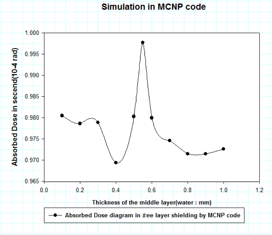
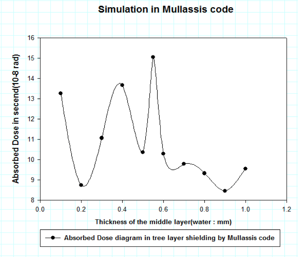
In the next step, by adding a middle layer of water, the simulations were performed in MCNP and MULLASSIS codes, and after checking the output of the software, it was found that the thickness of 0.55 mm for water as the middle layer and 0.45 mm for polyethylene as the last layer, the highest amount of absorbed dose was recorded in both codes (Figs. 5 and 6). Therefore, by examining the results, it wcan be concluded that the most optimal mode for a three-layer shield with a thickness of 1.6 mm is the simulation mode F in Table 2.
3. RESULTS
By comparing graphs (Figs. 5 and 6), we can conclude: firstly, the output of both simulations are consistent. Secondly, in the thicknesses of 0.45 mm for polyethylene as the first layer of protection, 0.55 mm for water as the middle layer and 0.6 mm for aluminum as the inner layer of protection, the maximum absorbed dose was obtained and it was calculated to be approximately 2.09 times that of the two- layer protection mode.
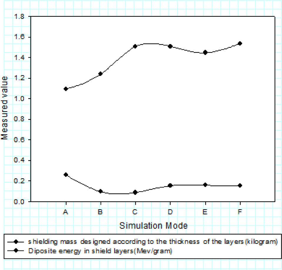
In the design of the shield, it is attempted to make the thickness of the layers of materials with higher density as less as possible so that the mass of the shield is optimized. For this purpose, the number of available combination cases of different layer thicknesses have been considered which can be seen in Table 3. Taking the importance of mass into account and if installing electronic parts can be nonobligatory, the use of multi-layer protection is very effective in reducing the mass. Moreover, among all considered modes, having a higher attenuation than aluminum in reducing the mass, the F mode, which is the most favorable mode, has a mass reduction percentage of 39.69.
4. CONCLUSIONS
In order to reduce the destructive effects of space radiation on the electronic components of satellites or spacecraft, it is essential to use radiation shields. Meanwhile, shielding mass is an essential factor in designing the body of satellites. Accordingly, in this work, multi-layer shields made of polyethylene, water and aluminum were investigated to protect parts in space missions and compared with other common shield materials (such as aluminum). The results indicated that if there is no requirement to use single-layer aluminum boxes to place electronic components inside, the use of multi-layer shielding -introduced in this work- can reduce the absorbed dose of the shielding layers by 35.3% and 44.1% respectively, for double-layer shielding (aluminum, polyethylene) and three-layer (aluminum, water, polyethylene). In addition, this can be effective in protecting electronic components as well. It was also found out by calculations that the mass of the two-layer and three-layer shield was reduced by 38.88% and 39.69%, respectively, compared to the corresponding aluminum shield, and a lighter shield with better efficiency was designed (Fig. 7).
